Product Features
-
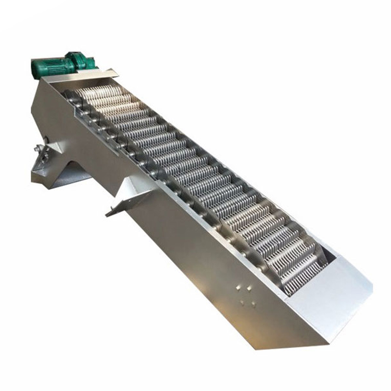
1. High-Performance Drive: Equipped with a cycloidal or helical gear reducer for smooth operation, low noise, large load capacity, and high transmission efficiency.
-
2. Compact & Modular Design: Easy to install and relocate; self-cleaning during operation and low maintenance requirements.
-
3. Flexible Control Options: Can be operated locally or remotely, depending on project needs.
-
4. Built-In Protection: Integrated overload protection automatically stops the machine in case of malfunction, protecting internal components.
-
5. Scalable Design: For widths exceeding 1500 mm, parallel units are installed to ensure structural integrity and screening efficiency.
Typical Applications
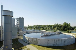
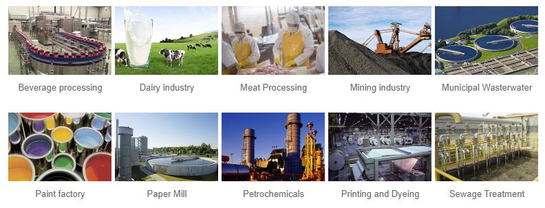
This automatic mechanical screen is widely used in municipal and industrial wastewater treatment systems for continuous debris removal. It is ideal for:
-
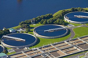
✅Municipal sewage treatment plants
-
✅Residential sewage pretreatment
-
✅Pumping stations and waterworks
-
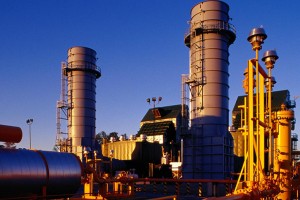
✅Power plant intake screening
-
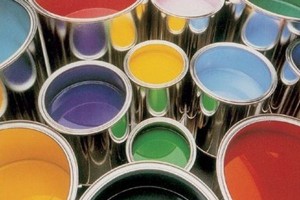
✅Textile, printing & dyeing industries
-
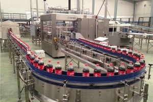
✅Food & beverage processing
-
✅Aquaculture and fisheries
-
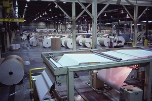
✅Paper mills and wineries
-
✅Slaughterhouses and tanneries
This unit plays a vital role in protecting downstream equipment, reducing maintenance costs, and improving overall system performance.
Technical Parameters
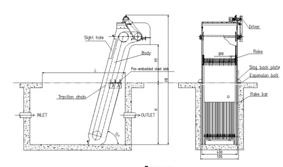
| Model /Parameter | HLCF-500 | HLCF-600 | HLCF-700 | HLCF-800 | HLCF-900 | HLCF-1000 | HLCF-1100 | HLCF-1200 | HLCF-1300 | HLCF-1400 | HLCF-1500 | ||
| Device Width B(mm) | 500 | 600 | 700 | 800 | 900 | 1000 | 1100 | 1200 | 1300 | 1400 | 1500 | ||
| Channel Width B1(mm) | B+100 | ||||||||||||
| Effective Grille Spacing B2(mm) | B-157 | ||||||||||||
| Anchor Bolts Spacing B3(mm) | B+200 | ||||||||||||
| Total Width B4(mm) | B+350 | ||||||||||||
| Teeth Spacing b(mm) | t=100 | 1≤b≤10 | |||||||||||
| t=150 | 10<b≤50 | ||||||||||||
| Installing Angle α(°) | 60-85 | ||||||||||||
| Channel Depth H(mm) | 800-12000 | ||||||||||||
| Height Between Discharge Port and Platform H1(mm) | 600-1200 | ||||||||||||
| Total Height H2(mm) | H+H1+1500 | ||||||||||||
| Back Rack Height H3(mm) | t=100 | ≈1000 | |||||||||||
| t=150 | ≈1100 | ||||||||||||
| Screen Speed v(m/min) | ≈2.1 | ||||||||||||
| Motor Power N(kw) | 0.55-1.1 | 0.75-1.5 | 1.1-2.2 | 1.5-3.0 | |||||||||
| Head Loss(mm) | ≤20(no jam) | ||||||||||||
| Civil Load | P1(KN) | 20 | 25 | ||||||||||
| P2(KN) | 8 | 10 | |||||||||||
| △P(KN) | 1.5 | 2 | |||||||||||
Note:Pis calculated by H=5.0m,for every 1m H increased,then P total=P1(P2)+△P
t:rake tooth pitch coarse:t=150mm
fine:t=100mm
| Model /Parameter | HLCF-500 | HLCF-600 | HLCF-700 | HLCF-800 | HLCF-900 | HLCF-1000 | HLCF-1100 | HLCF-1200 | HLCF-1300 | HLCF-1400 | HLCF-1500 | ||
| Flow Depth H3(m) | 1.0 | ||||||||||||
| Flow Velocity V³(m/s) | 0.8 | ||||||||||||
| Grid Spacing b(mm) | 1 | Flow Rate Q(m³/s) | 0.03 | 0.04 | 0.05 | 0.06 | 0.07 | 0.08 | 0.08 | 0.09 | 0.10 | 0.11 | 0.12 |
| 3 | 0.07 | 0.09 | 0.10 | 0.12 | 0.14 | 0.16 | 0.18 | 0.20 | 0.22 | 0.24 | 0.26 | ||
| 5 | 0.09 | 0.11 | 0.14 | 0.16 | 0.18 | 0.21 | 0.23 | 0.26 | 0.28 | 0.31 | 0.33 | ||
| 10 | 0.11 | 0.14 | 0.17 | 0.21 | 0.24 | 0.27 | 0.30 | 0.33 | 0.37 | 0.40 | 0.43 | ||
| 15 | 0.13 | 0.16 | 0.20 | 0.24 | 0.27 | 0.31 | 0.34 | 0.38 | 0.42 | 0.45 | 0.49 | ||
| 20 | 0.14 | 0.17 | 0.21 | 0.25 | 0.29 | 0.33 | 0.37 | 0.41 | 0.45 | 0.49 | 0.53 | ||
| 25 | 0.14 | 0.18 | 0.22 | 0.27 | 0.31 | 0.35 | 0.39 | 0.43 | 0.47 | 0.51 | 0.55 | ||
| 30 | 0.15 | 0.19 | 0.23 | 0.27 | 0.32 | 0.36 | 0.40 | 0.45 | 0.49 | 0.53 | 0.57 | ||
| 40 | 0.15 | 0.20 | 0.24 | 0.29 | 0.33 | 0.38 | 0.42 | 0.46 | 0.51 | 0.55 | 0.60 | ||
| 50 | 0.16 | 0.2 | 0.25 | 0.29 | 0.34 | 0.39 | 0.43 | 0.48 | 0.52 | 0.57 | 0.61 | ||


